
2026 How to Choose the Best CNC Flattening Bit?
Choosing the right Cnc Flattening Bit in 2026 can mean the difference between a smooth spoilboard and hours of sanding. It also affects cut quality, tool life, and machine load. Grand View Research estimated the global CNC machine market at USD 83.99 billion in 2023, with projected growth through 2030 (CNC Machine Market Size, Share & Trends Analysis Report). That broader market figure reflects expanding CNC use, not demand for flattening bits specifically. Important distinction.
For a practical choice, match the bit’s diameter and cutting length to your router’s power, collet, and work area. Check the manufacturer’s recommendations for feed rate and spindle speed. Carbide grade, flute layout, and cutter geometry also influence chip evacuation and surface finish. On a large MDF spoilboard, a wider bit may cover more ground per pass, but it can place greater demands on the machine. Wider is not always better. Runout, dull edges, and an aggressive depth of cut can leave ridges even with a premium cutter. I’ve seen tool selection treated like a shortcut; in practice, setup matters just as much. This guide compares the details that deserve attention, explains where common choices can disappoint, and helps you select a bit for your machine and material—not just the product label.
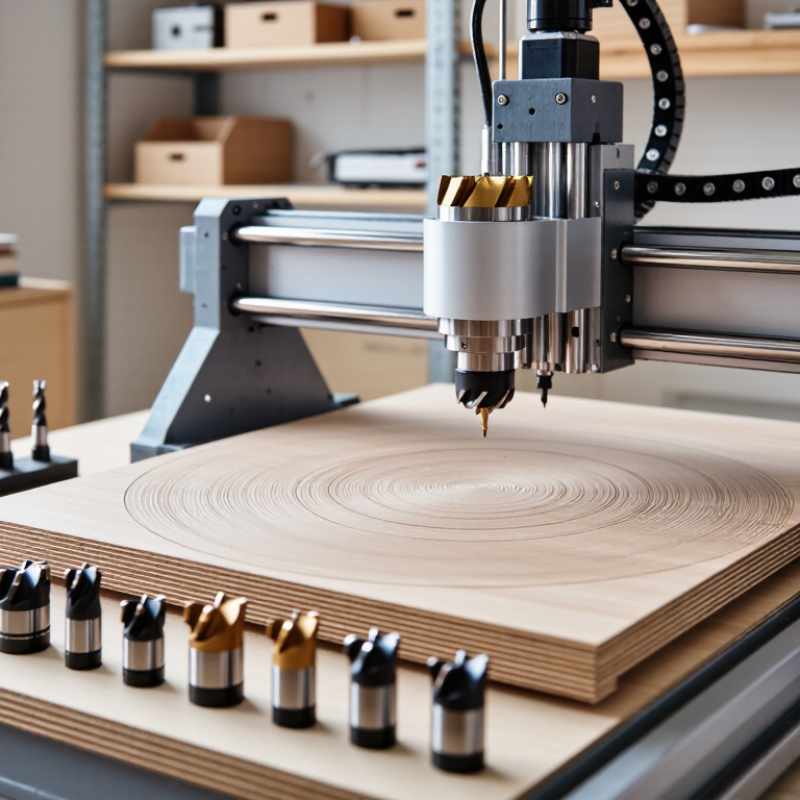
Identify CNC Flattening Bit Types: Inserted-Carbide vs. Solid-Carbide
A CNC flattening bit must remove material evenly without leaving ridges across a wide surface. The two common choices behave differently. Inserted-carbide bits use replaceable cutting edges mounted in a steel body. They are often practical for larger flattening jobs, where an edge may dull after repeated passes over hardwood or plywood.
When an insert wears, you can usually rotate or replace it instead of discarding the whole cutter. Check that each insert sits cleanly and securely; a tiny chip or uneven setting can leave a visible track. Small detail matters. Inserted bits can be economical over time, though replacement inserts and setup still add cost. They are not automatically the best choice for every machine or material.
Solid-carbide bits are made from one piece of carbide and can offer a compact cutting profile for smaller work. Their continuous edge may leave a clean surface when the tool, feed rate, and machine are well matched. But carbide is hard and brittle. A collision with a clamp or a deep, aggressive pass can damage the cutter rather than simply dull it. Not indestructible. Before choosing, compare the bit diameter with your machine’s capacity, then consider how often you flatten stock and how easily you can maintain the cutting edges. The distinction is useful, but not perfectly simple: material, setup, and operator habits can change which option performs better.
| Selection Factor | Inserted-Carbide Flattening Bit | Solid-Carbide Flattening Bit |
|---|---|---|
| Cutting-edge construction | A steel or alloy body carries separate carbide inserts secured with screws. Insert shape and replacement method vary by design. | The cutting portion is made from one piece of carbide. The cutting edges are integral to the tool rather than replaceable inserts. |
| Common size range | Often available in larger surfacing diameters, commonly around 1–3 in (25–76 mm), depending on the tool and machine. | More commonly found in smaller diameters. Large solid-carbide surfacing tools are less common because of material cost and tool weight. |
| Best suited to | Flattening slabs, spoilboards, and other broad surfaces where a larger cutting diameter and replaceable edges are useful. | Smaller surfacing tasks or setups that benefit from a compact, rigid cutting tool and a continuous carbide cutting edge. |
| Edge maintenance | Worn or damaged inserts can usually be replaced individually. Some designs allow inserts to be rotated, but this depends on the insert geometry. | There are no separate inserts to replace. A worn edge generally requires professional regrinding or replacement of the tool. |
| Cost considerations | The initial tool may cost more than a simple small bit, but replacing individual inserts can reduce the cost of restoring the cutting edges. | Small tools can be economical, but larger solid-carbide tools use more carbide and may have a higher replacement cost. |
| Rigidity and machine demands | The larger body can cover more area per pass, but the machine must have adequate clearance, spindle capacity, and workholding for the tool’s diameter and mass. | Smaller tools generally place less demand on clearance, but the appropriate feed, speed, and depth of cut still depend on the tool and machine. |
| Surface finish | Can produce a clean, level surface when inserts are sharp, correctly seated, and set to a consistent height. Uneven insert height can leave ridges. | Can produce a clean surface when sharp and properly set up. Finish depends on tool geometry, runout, feed rate, step-over, and workpiece material. |
| Key setup checks | Confirm the inserts are secure and clean, check that cutting edges sit evenly, and use the manufacturer’s recommended operating limits. | Check collet condition, tool runout, shank compatibility, and the tool’s rated operating limits before machining. |
| Practical trade-off | Often a practical choice for frequent, wide-area surfacing when replaceable cutting edges are a priority. | Often a practical choice for smaller-scale work when a compact one-piece carbide cutter fits the job and machine. |
| Selection note: Diameter ranges and typical uses are general market examples, not universal specifications. Choose a cutter compatible with the CNC spindle, collet, work material, and manufacturer’s speed and feed recommendations; always use appropriate guarding and dust extraction. | ||
FAQS
It describes how quickly the cutting edge moves across the material. The result is measured in meters per minute.
Use V = πDN ÷ 1,000. D is the cutting diameter in millimeters, and N is spindle speed in RPM.
No. Use the actual cutting diameter. The shank size can be different.
About 679 m/min. Compare that figure with the recommended range for your material and tool.
Try 40–60% of the cutter diameter. For a 50 mm cutter, that is about 20–30 mm between lanes.
A smaller step-over usually leaves a smoother finish but takes longer. A larger one works faster and may leave visible scallops.
Listen for steady cutting and watch for burning or chatter. Inspect the surface under raking light for raised strips.
Not safely by assumption. Feed rate must also suit the tool and material. I would adjust cautiously; one clean-looking pass proves little.
Trapped debris can mark the work or affect the cut. Dust matters. Also check runout and machine alignment if ridges remain.
Conclusion
Choosing the best Cnc Flattening Bit starts with matching its construction to the work. Inserted-carbide cutters offer replaceable cutting edges, while solid-carbide options provide an integrated cutting body. Consider the material, expected use, and maintenance preferences when comparing them. Next, select a cutter diameter that your machine can handle and that suits the width of the workpiece; a larger cutter may cover more area per pass, but it must remain within the machine’s capacity.
Set the spindle speed using the cutting-speed relationship V = πDN ÷ 1,000, where V is cutting speed in meters per minute, D is cutter diameter in millimeters, and N is spindle speed in revolutions per minute. For efficient coverage, begin with a step-over around 40–60% of the cutter diameter and adjust as needed for the finish and setup. Before cutting, inspect insert geometry and confirm that the shank fits the collet securely. Check all dimensions and connections with the machine stopped, then make a cautious test pass.